ADVANCED DRY ROOM CONCEPTS
PRESENTED BY ROBERT S. SMITH, JR.
NATIONAL SALES MANAGER
AT THE FIRST BATTERY TECHNOLOGY SYMPOSIUM ON ADVANCED SECONDARY BATTERIES
SEOUL , KOREA DECEMBER 12, 1996
ABSTRACT
Battery Manufacturing with lithium foils and other moisture sensitive
materials for lithium ion rechargeable cells have required the utilization
of ultra-low humidity dry rooms since lithium battery development began in
the early 1970's. All primary lithium battery dry rooms are maintained at 2%
RH or less, which is equivalent to a -28 ° C dewpoint, or drier. Critical
materials for lithium ion batteries, including polymer electrolytes and lithiated
carbons sometimes require dewpoints as low as -60 ° C (10 ppmu). For most
manufacturers the original emphasis concerned dry room performance because
of the safety requirements for handling batteries and products assembled with
lithium foil. As the commercialization of rechargeable lithium batteries increases,
the operating costs and energy requirements of dry room mechanical systems
must be considered. Additionally, as new Li Ion and lithium polymer type batteries
are developed, the requirement for dry rooms at 1% RH or less zones (-34 ° C
dewpoint or less) with -60ºC dewpoint has been increasingly expressed
by manufacturers. Desiccant dehumidification systems utilizing a variety
of existing and new desiccants are discussed, as are potential energy saving
opportunities in the design of dry room systems.
INTRODUCTION
Proper dry room design and construction requires careful consideration
of vapor barriers provided with the structure, moisture loads from occupants,
exhaust air requirements, door openings at air locks, and an understanding
of regional climate data for determining make up air design temperatures
and dewpoints. Combined with an understanding of these variables, the designer
can select the mechanical components correctly matched to the application
requirements and provide ultra dry conditions, along with energy modulation,
to use the least possible amount of energy. Although each dry room and its
design requirements demand a custom design approach, since the variables
which define the moisture load can be measured, and the selection of available
mechanical systems available is finite, the decisions from an equipment selection
standpoint for dehumidification, refrigeration, heating, and total airflow
follow a similar pattern for each project.
Prior to discussing energy saving opportunities and new desiccants, some of the basics of dry rooms must be defined.
Moisture Loads:
Dry room design requires an understanding
of the total internal moisture load and external moisture load from make
up air that will be processed through the mechanical conditioning system.
Fig. 1 indicates the various loads which must be considered in all dry room
designs.
|
The moisture load from occupants is the greatest concern, although it is fairly predictable. Based on the performance of over 70 ultra dry rooms we have designed over the last 20 years, we can predict with confidence that the moisture load from people is approximately 1200 to 1500 grains per hour per person of moisture. Since 7000 grains per hour equals one pound of water, if we assume 1500 grains per hour per person, a room with 20 occupants would result in a moisture load from occupants of 30,000 grains per hour.
The second critical variable for moisture load is the exhaust air and air for pressurization. The cardinal rule for all dehumidification systems for dry rooms or for other applications at higher dewpoints, is "the greater the exhaust volume, the greater the refrigeration requirement for make up air pre-cooling, and therefore, the higher the energy cost". For ultra-low dry room design, we limit the total make up air to no greater than 49% of the total volume of the air being processed into the room. Therefore, a system processing 6000 CFM of air, which would control a room at 2% RH or less, with 24 people, would be limited to a make up air volume of 2,935 CFM. As we will discuss later, because of the requirements for low dewpoint air for dehumidifier reactivation air, a system with a total make up air volume of 2,935 CFM requires a reactivation air volume of 1,545 CFM, depending upon the return air conditions to the system. This allows the battery manufacturer a total process exhaust volume of no greater than 1,091 CFM, assuming we allow 300 CFM for room pressurization.
Moisture loads through door openings in air locks are important, but are relegated to a lower priority since in all Harris drly room designs we purge the air locks with dry room air. We have found that this limits the infiltration of outside air by maintaining the dry room at a positive pressure. It by no means eliminates the moisture load through door openings since vapor pressure is not equivalent to positive pressure. In all cases, where a vapor pressure differential exists between two spaces, the moisture from the space at the higher moisture content will attempt to infiltrate the area at the lower moisture content.
The fourth moisture load is vapor transmission through structures. This can be eliminated to virtually zero if we use a metal clad insulated panel structure typical of all Harris dry rooms, and many others throughout the world. If you attempt to build a dry room with traditional building construction materials such as gypsum board, or concrete block, or clean room panels, it is necessary to calculate the vapor transmission losses through these systems. Since it is virtually impossible to provide a vapor barrier equivalent to the modular insulated panel systems with traditional construction materials, most manufacturers choose to build dry rooms witih insulated panels because of the ease of construction, modularity of approach, (which allows for future expansions), and the ability to easily relocate the dry room if this is necessary.
Dry Room Structures:
Why metal clad insulated panels?
Most battery manufacturers and lithium foil processors choose to build dry rooms with these panel systems for the reasons stated in the previous paragraph. Fig. 2 summarizes these issues more clearly, and highlights the features provided with modular panels. Metal clad modular panel dry rooms are suggested for all lithium battery manufacturers wishing to limit dry room moisture infiltration.
Air locks for dry rooms should be of adequate size to allow easy egress by occupants without both doors being open at the same time. Some manufacturers use mechanical interlocks to eliminate this possibility from occurring, but we do not recommend this because of the potential possible failure with mechanical interlocks, especially during emergency situations. We prefer having owners train their employees in the proper use of the dry room, and possibly install red light/green light systems at doors to alert the occupants on proper procedures for entering/exiting the dry room. Note: For high humidity climates, including most of Asia , we recommend that owners use double airlocks to further limit moisture infiltration. This is especially important when the building housing the dry room is not air conditioned or when air conditioning is shut off for part of the day.
|
Sealed Openings:
It is absolutely imperative that all penetrations into the dry room structure
be completely sealed, preferably with foam-in-place urethane or silicone.
This includes conduit penetrations, which must also be sealed within the
pipe, other process pipe systems entering the dry room, and convenience openings
for telephone, communications, etc. It is best to limit the number of penetrations
and gang them in a central spot high in the room structure, preferably near
the roof panels if this is possible.
Floor covering within the dry room can consist of either (a) sheet vinyl floor covering, (b) conductive tiles or, (c) a sealed concrete floor. All of these options have been successful in limiting the moisture permeation through concrete slabs, which create another source of moisture infiltration into the dry room. In the early 70's dry rooms were built with insulation buried in the concrete floors. Although this practice is acceptable and provides the optimal solution for limiting vapor transmission through the concrete slab, its excessive cost has virtually eliminated it from practical usage in today's marketplace.
Fig. 3 provides a section view of a typical dry room showing a suspended ceiling and penetrations entering the plenum, as well as a drawing of an air lock common to the corridor and the dry room.
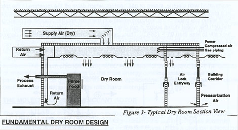
FUNDAMENTAL DRY ROOM DESIGN
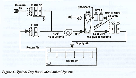
Fig. 4 indicates a traditional dry room mechanical system flow schematic.
In this schematic a mixture of outside make up air and return air are both
pre-cooled to a temperature of approximately 42 ° F (5.5ºC). Please
note, the two make up air coils in series provide a lead/lag coil situation
on make up air to provide one method of energy savings. The lead cooling
coil is set up to provide the majority of the make up air dehumidification
and the lag coil will operate only on humid days when the ambient dewpoint
conditions require maximum latent moisture stripping with the make up air
coils.
The make up and return air streams blend together at the supply fan and then enter into the desiccant rotor. Within the rotor, either lithium chloride, synthesized silica gel, HPX or molecular sieve desiccant will be used to absorb moisture from this process air stream. The discharge from the dehumidification rotor will then be either cooled or heated to provide comfort conditions.
You will notice in this figure we are showing a purge sector, which takes a portion of the process air off the rotor, back to the reactivation heaters. This is an energy saving feature, which also results in extremely low dewpoints for ultra dry room applications. The use of the purge dehumidifier is based on the fact that the process air leaving the rotor is extremely stratified in temperature and humidity. The purge takes the sector of the wheel having the highest moisture content (dewpoint) and temperature and separates its from the dryer and cooler air off the wheel discharge. This moist (approximately 1 gr/lb) and hot air (approximately 53ºC to 56ºC air) from the purge sector passes back into the wheel just after it rotates out of the reactivation sector and into the process air sector of the wheel. The wheel at this point is still hot from being reactivated with electric, steam or gas heaters, which drive off the moisture in the rotor at a temperature requirement of between 280 to 300 ° F (138ºC to 149ºC). The residual heat within the mass of the structure remains in the rotor and the process air passing through the wheel in this sector is not dried efficiently until the desiccant is cooled typically to less than 95 ° F (35ºC). Thus, by using a purge sector in the first 25 degrees of wheel rotation after leaving reactivation, we provide no reduction in desiccant dehumidification performance and provide reactivation energy savings, as well as a source of dry reactivation air necessary for ultra dry applications.
DESICCANTS UTILIZED - NEW AND OLD
The original dry rooms utilized for process applications used dual
tower molecular sieve, or activated aluminum systems whereby one desiccant
tower was in the process air stream while the other tower was in the reactivation
air stream being desorbed. These systems are somewhat effective although
leakage exists at the valves circulating air between the two towers, which
are switched on a time basis to allow each cylinder to go into reactivation
as its dehumidifying performance is depleted. The advent of the lithium chloride
desiccant impregnated Honeycombe wheel, introduced by Cargocaire Engineering
in the U.S. , and Munters in Europe in 1960, provided engineers with a new
type of dehumidifier with a tremendous capacity for moisture absorption.
This dehumidifier allows two continuous counterflow air streams of reactivation
and process dry air to be maintained to provide a consistent effluent off
the rotor.
THE LITHIUM CHLORIDE DESICCANT ROTOR
Lithium chloride has many attractive features as a desiccant for ultra
dry applications. When impregnated into the fiberglass fluted honeycomb structure,
its ability to absorb moisture from the process air and exhaust this moisture
to a reactivation air stream can be repeated indefinitely. Lithium chloride
is not dependent for its water absorption capability upon a specific pore
system, which could be blocked by pollutants, or which can undergo changes
with time as can occur with the granular desiccant systems. The lithium chloride
rotors high degree of porosity, large internal surface, low weight, and insignificant
reactivation heat carryover provide attractive features for a dry room system.
The lithium chloride impregnated wheel has, for thirty years, been the system
of choice for engineers looking for the most energy concious, reliable, and
well packaged industrial dehumidifier for process applications. Since 1992,
new alternative desiccants to the lithium chloride rotor have emerged.
THE MOLECULAR SIEVE DESICCANT ROTOR
The first alternative is the Cargocaire molecular sieve wheel, which
utilizes molecular sieves less than 4 angstroms in size impregnated into the
same fiberglass substrate utilized for the lithium chloride rotor. The molecular
sieves utilize a physical adsorption process whereby water vapor is attracted
and held to the walls of many pores within the structure, and then reactivated
during high temperature reactivation. The molecular sieve wheels have the
ability to provide slightly lower dewpoints than lithium chloride wheels,
but at the expense of higher energy costs for final sensible cooling to the
dry room and a 10% higher pressure drop through the rotor. With molecular
sieves, if the drier is overloaded with moisture there will be no structural
failure and loss of desiccant, which can occur in lithium chloride wheels
when the mass loading exceeds the capability of the reactivation energy to
remove the total quantity of moisture required for proper system operation.
THE SILICA GEL DESICCANT ROTOR
The second choice is the synthesized silica gel unit designed and
sold by Seibugiken Munters and Cargocaire separately. The Seibugiken rotor
is a Japanase manufactured wheel, which has been marketed in the USA for approximately
10 years. This system utilizes a ceramic corrugated paper to manufacture
flutes packaged into a wheel. The ceramic in the structure provides structural
support for the thin layer of sythesized silica gel added to the system.
The silica gel is bonded to the ceramic substrate and fills all voids within
the ceramic fiberglass structure.
Similar to molecular sieve rotors, the silica gel rotor uses a physical adsorption process whereby water vapor is captured at the surface of the silica gel and then drawn into the micro pores by capillary action. In this process the moisture converts adiabatically from vapor to liquid.
The Cargocaire silica gel rotor is similar to the ATS silica gel rotor in that a proprietary customized silica gel is utilized for impregnating the rotor to accurately control the pore characteristics of the desiccant. This results in ideal drying performance over a wide range of applications.
The advantages of the silica gel desiccant rotor include (a) being an insoluble desiccant, it is not possible to "wash out" the desiccant from the wheel as can occur with lithium chloride, (b) the permanent nature of the desiccant makes it possible to literally wash the wheel in water if particulates block the air passageways, (c) like the lithium chloride rotor the inorganic composite structure of these rotors do not support combustion. Note: Harris Environmental has on several occasions found rotors on fire due to problems with reacativation circuits.
For lithium battery dry room operations the silica gel wheel is not a suggested alternative since its ability to produce ultra low dewpoints is not as great as the lithium chloride and molecular sieve wheels. A combination silica gel/molecular sieve wheel can be considered for low dewpoint applications.
HPX COMBINATION DESICCANTS
In early 1994 Harris Environmental Systems began installing systems
with combination desiccants, known as the HPX Desiccant Wheel manufactured
by Munters Cargocaire to provide ultra-low dewpoints, as well as provide more
moisture removal for a given size rotor. The HPX wheel is a dual wheel within
one rotor encasement, which is a combination molecular sieve and silica gel
wheel that can provide dewpoints as low as -60ºC (.047 gr/lb, 10.6 ppmv).
Like the molecular sieve molecular wheels, HPX is a physical adsorbent specifically
tailored to each application by engineering the desiccant pore system to
maximize moisture absorption efficiency. The HPX desiccant does not undergo
any chemical or physical change during the adsorption process and can be
washed with water if required. The inherent advantages in HPX rotors over
lithium chloride rotors are as follows:
- A 10 year life expectancy versus a 5 year life expectancy with lithium chloride.
- The wheel can be washed if it is dirty or contaminated, whereas lithium chloride wheels cannot be physically washed in the field.
- The ability of the HPX rotor to provide equivalent dewpoints with 50% more air volume. With HPX, a 50% higher face velocity across the wheel allows a given size rotor to provide 50% more moisture removal for a minimal increase in price.
- The utilization of a HPX wheel in lieu of a lithium chloride wheel allows each dry room to have more user exhaust if required, due to the increased air volume capabilities inherent in the HPX system design. As an example, with lithium chloride, the largest system we typically provide is a 6,000 CFM system providing 4,500 CFM of supply air and allowing 1,091 CFM exhaust, which at 2%RH or less, would be equivalent to 23 people. The same size rotor and desiccant drier with an HPX wheel can process 9,000 CFM of air, supply 6,635 CFM through the dry room, allow 1,738 of user exhaust, and allow 35 people to operate in the dry room at 2%RH or less. This increase in performance does increase the total system size and system cost with a respective increase in refrigeration capacity from approximately 60 HP of refrigeration to 110 HP refrigeration. However, this performance increase of 50% more moisture removal for a given size rotor is attained at a mimimal first cost increase.
The ability to supply air at 10.6 ppm has led to the development of Harris dry box enclosures over critical process machinery which provide point source dry air at critical zones. These enclosures allow “glove box” type conditions in the enclosure while allowing air to return back to the room to maintain the dewpoint at the required condition for occupancy. Lithium chloride wheels can only supply 50 ppmv dry air, whereas the HPX wheels allow us to achieve 10.6 ppm, thus creating conditions similar to those found in glove boxes.
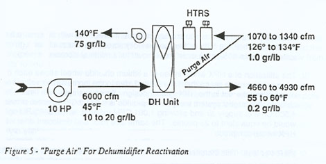
ENERGY COSTS: 6000 CFM DEHUMIDIFICATION SYSTEM
For purposes of discussion we have utilized a 6000 CFM system as shown
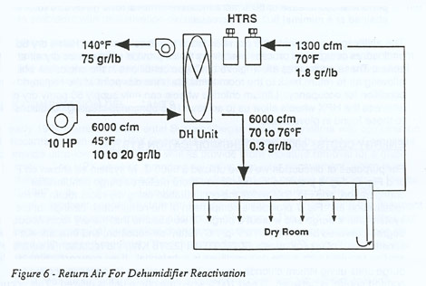
on Fig. 5 and Fig. 6. Fig. 5 provides the newer and more preferred purge
dehumidifier configuration, and Fig. 6 provides the configuration using dry
room return air for reactivation air. Fig. 7 provides a comparison of the
refrigeration savings for the system with a purge and without a purge. If
we assume that the dry room needs 55 degree delivered air to hold a 70 ° F
(21ºC) return air condition, and thus allow a room sensible load of
approximately 77,760 BTUH (22.78 KW), the reduction in sensible cooling required
with purge dehumidifiers is substantial. If we compare purge and no purge
units using lithium chloride wheels, the net savings for sensible cooling
for comfort control is between 70 and 100% when the purge unit is utilized.
This occurs because the discharge temperature off the rotor is approximately
15 degrees higher when no purge is utilized versus when a purge is utilized.
The reason for this is that the latent heat of absorption which occurs during
the desiccant dehumidification process is
|
||||||||||||||||||||
REACTIVATION ENERGY SAVINGS WITH PURGE DRIERS
Fig. 8 provides an analysis showing two lithium chloride based dehumidification
systems, one without a purge and one with a purge, with varying inlet conditions
of 45 ° F (7.2ºC) at 20 grains, 15 grains, and 10 grains. Please
note that the change in inlet moisture conditions in grains per pound is
dependent on the percentage of make up air versus return air as well as the
expected moisture load present in the dry room.
|
||||||||||||||||||||
As can be seen from this figure, as the inlet absolute moisture content to the rotor decreases, the reactivation energy requirement is reduced and the air volume required to optimally desorb the wheel decreases. Assuming both systems are heated to 280ºF (138ºC) for proper reactivation and provide 140ºF (60ºC) reactivation outlet conditions, the reactivation energy savings with purge dehumidifiers provides an average savings of 29% in terms of BTUH or KW input. Similar to the sensible cooling analysis, purge driers provide lower operating costs than systems without a purge, and thus this could be reflected in the variable costs of manufacturing each lithium cell.
|
|||||||||||||||
HEAT RECOVERY OF REACTIVATION AIR
Another possible means of providing energy reduction in operating
a lithium battery dry room system is to utilize a heat recovery unit to heat
the incoming reactivation air to reduce energy consumption. This can be accomplished
either by utilizing a cross flow plate exchanger or a heat pipe, which takes
the heat from the reactivation air discharge and transfers it to the reactivation
air inlet. Another option is to install a hot gas condenser coil in the reactivation
inlet to take energy from the refrigeration compressors continually operating
and transferring this energy to the reactivation inlet. The heat pipe or
plate exchanger energy savings are not possible for purge units because of
the closed loop nature of the reactivation circuit, which takes hot, dry
air from process directly to reactivation.
With heat recovery, a system utilizing rom air for reactivation at 2ºC (70ºF) can recognize preheated reactivation at 14ºC to 20ºC (25ºF to 35 ° F), since the reactivation exhaust air is maintained at 49ºC (120 ° F) as a minimum. This will provide an energy savings of 12 to 16%, but is not as effective as using a purge, which reduces reactivation energy consumption by typically 29%. The payback of utilizing a heat pipe or plate exchanger will be four to five years for the typical lithium battery dry room system.
For larger dry rooms without purge dryers, which have one compressor or more running virtually all the time, the best heat recovery option may be to utilize a hot gas heat reclaim coil to preheat reactivation air. With a hot gas reclaim coil, return hot gas from the refrigeration system will discharge heat in a condenser coil located within the custom dehumidification system. The efficiency of this type of heat reclaim varies based on the operating conditions of the system and the total refrigeration capacity in use at any one time. Since all Harris systems utilize compressor unloading to reduce energy consumption, the total amount of hot gas available for condenser coil heat reclaim can not be predicted accurately as each application varies based on internal sensible heat load, outside air ambient conditions, and the operating characteristics of each refrigeration system. On a generalized basis, it is fair to expect that when the hot gas reclaim coil is operating efficiently, an efficiency of 50% will allow the temperature rise in the return air to reactivation to increase from 70 ° F to 95 ° F. The engineer must be cautioned that this 95 ° F pre-heated increased temperature from heat reclaim for the reactivation circuit will not exist on a constant basis and, therefore, the system should be designed with full reactivation energy input assuming no heat reclaim was available.
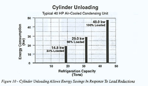
COMPRESSOR UNLOADING
For the 6000 CFM system used in the previous example, which would
maintain 2% RH for the room having 21 to 26 occupants, in most North American
applications we would have between 40 to 60 HP refrigeration with the final
number based on the total make up air and outside ambient design conditions.
This refrigeration system is complex in nature and typically involves multiple
compressors each with cylinder unloading capability to reduce energy consumption.
Traditionally, the compressor will have cylinder unloading to allow operation
at 100%, 66%, 33% capacity and complete shutdown. This will allow the amperage
draw from the compressor to vary based on evaporator setpoint conditions and
refrigeration demand requirements. As with heat reclaim coils, energy savings
due to compressor unloading are difficult to predict since the demand for refrigeration
capacity will vary depending upon internal sensible load, multiple or single
shift operations, and the outside ambient air conditions.
Practically speaking, the higher the outside humidity, the greater refrigeration capacity that is demanded for make up air pre-cooling. Return air pre-cooling is fairly constant since we typically have return air at 21ºC (70ºF), which is pre-cooled to 5ºC (45ºF) degrees F. The aftercooling will vary widely based on actual room internal sensible heat loads, which can demand either heating or cooling. In conclusion, the battery manufacturer and engineer of the dry room system should always specify compressor unloading with any refrigeration system operational with the dry room. Fig. 10 depicts the energy swings of compressor part load operation with unloading.
As a side note to this discussion, it is fundamental that a direct expansion refrigeration system be utilized, and not a chilled water system for dehumidification pre-cooling based on the limitations of typical chilled water systems. Traditional building chilled water systems deliver chilled water at 42ºF to 45ºF (5ºC to 7ºC), which with a typical 10ºF rise across the coil will provide an air leaving temperature of 52ºF to 55ºF (11ºC to 13ºC). Since desiccant systems operate most efficiently with the coldest process inlet conditions obtainable, chilled water sytstems are not the cooling system of choice. Direct expansion systems, however, can be safely operated at a 33ºF (.56ºC) saturated suction temperature, which is just above freezing, and provide a 42ºF (5.5ºC) leaving coil temperature. With a 2ºC rise for fan heat, the inlet condition can be predictably maintained at 7.2ºC (45ºF) at the desiccant rotor. The design of the refrigeration system to maintain this saturated suction temperature requires tremendous expertise in refrigeration system design and should never be overlooked in the decision making procedure when procuring or upgrading a dry room system.
REACTIVATION ENERGY - A CRITICAL CHOICE
Fig. 11 provides typical energy costs associated with operating a
6000 CFM desiccant rotor with typical utility rates for gas and electricity.
Obviously the total dollar cost will vary depending on the utility rate in
your community.
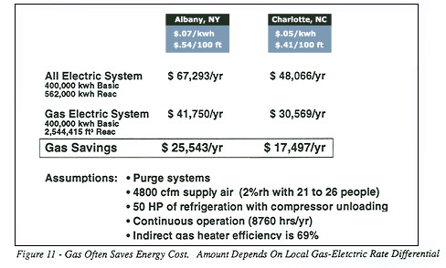
For this example we have assumed 8760 hours of system operation with no energy modulation on the reactivation heaters utilized with the purge design system. In reality, energy modulation using a gas modulating valve for gas systems, or an SCR control on electric heaters for electrically reactivated units would be employed. However, without careful BTUH monitoring it is difficult on an average basis to predict the percentage of time energy modulation will be in effect. The purpose of Fig. 11 is to show how, in most cases, gas reactivated units provide lower energy costs than electrically reactivated systems. Electric reactivated systems are by far the easiest systems to install and are cheaper from a first cost basis than gas or steam systems which cost approximately 5 to 10% more. However, the favorable rate structure with indirect fired gas systems typically provides incentives to install a dry room system with gas or steam reactivation. Note: Systems with high pressure plant steam can also be installed assuming 50 psig steam is available year round.
MULTIPLE DESICCANT SYSTEM DESIGNS
The final option for production dry rooms is to consider utilizing
multiple systems in lieu of one dehumidification system optimally sized for
the moisture load. Fig. 12 shows (2) 3000 CFM systems versus (1) 6000 CFM system.
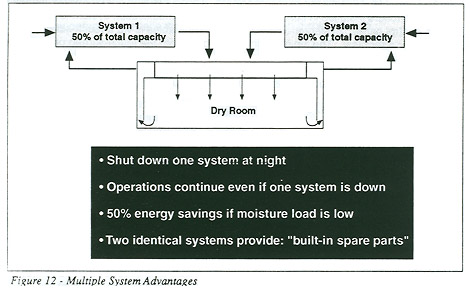
Although, all things being equal, the energy costs of running (2) 3000 systems would be slightly higher than (1) 6000 system because of the inefficiencies of motors, duplication of power feeds, etc., the ability to shut one system down when the people load is below the expected level and operate the dry room on one smaller system provides a distinct advantage for total energy consumption. For those battery facilities operating only one shift, the typical scenario would be to run all dehumidification systems from approximately 6:00 a.m. to 6:00 p.m. , and then have one system shut down on a time clock from 6:00 p.m. to 6:00 a.m. This will reduce the energy consumption from operating both systems 100% of the time by 50%. The first cost of having two smaller systems in lieu of one bigger system is greater, but in addition to obvious energy savings with this feature, the battery manufacturer is provided with 50% back up so that if one system were to fail in a dramatic fashion, the other system would be available to run the dry room at a partial load basis at all times. For production dry rooms, we encourage the utilization of two systems because of the energy saving features and the inherent system redundancy, which will allow partial mode operation should one system fail and servicing were not readily available.
DDC Controls For Dry Rooms
To provide greater control monitoring and reduce service costs, Harris
has been providing direct digital control “smart” control systems
with modem access to our facility in Andover , MA , USA for the past three
years. These systems operate with a variety of DDC controllers installed
in control panels at the dehumidification system and the dry room control
panel. System monitoring of critical variables is via a touch-screen monitor
or a terminal. The typical points monitored from the touch-screen or terminal
include the following:
- Leaving air temperature of precool coils at make up and return air.
- Blended air temperature entering the desiccant wheel.
- Discharge air temperature off the desiccant wheel.
- Room supply and return air temperature.
- Reactivation discharge temperature.
- Compressor suction temperatures.
- Discharge temperatures on each compressor.
- Discharge pressure at each condensing unit.
- Dewpoint control monitoring off system supply and return.
Individual screens for monitoring and controlling these functions with Harris designed software is now available for any dry room utilizing one or two D/H Series systems. In addition to the points mentioned above, other features and benefits that cannot be provided with stand-alone PID controllers in our dry room are as follows:
- A 10 to 20% operating savings for the condensing units during off-peak design conditions. All systems are designed to ASHRAE 1% weather data and as the operating conditions change and the DDC system will constantly optimize the operation of the condensing units.
- Provide the customer/user the ability to monitor, alarm, maintain and troubleshoot the operation of the dry room and mechanical equipment. This can be done on site by the customer, or remotely by the customer or Harris Environmental Systems. This can save valuable service downtime in the operation of the Dry Room and equipment.
- The ability to modify and change the operation of the dry room and equipment by program changes as customer requirements change.
- The ability to data log input temperatures, dewpoints, etc. throughout the DDC control system. The customer or service group can view these same inputs in “real time” - dynamic updating through the touch-screen display station.
- Easy operator interface through the touch-screen display station.
- User security protection both through touch-screen display and computer terminal.
SUMMARY
Lithium battery manufacturers have a much greater choice for new desiccants
and energy saving opportunities in the 90's than every before. Fig. 13 quickly
summarizes the decisions a manufacturer must consider.
(a) Should I install a purge system in lieu of my current system? Energy savings would be dramatic as shown earlier.
(b) Should I provide either a lithium chloride system or an HPX combination desiccant rotor? Energy costs with lithium chloride rotors are less, but delivered air dewpoints with HPX systems are much lower.
(c) Remember to always demand compressors with compressor unloading.
(d) Should I specify gas, steam, or electric reactivation? Gas reactivation appears to be the simplest, and usually the most cost effective choice.
(e) Should I request any heat recovery options beyond the purge design? Heat pipes and plate exchangers are quite expensive and hot gas reclaim coils have lower first costs than heat pipes or plate exchangers, but provide less energy savings.
(f) Should I specify dual systems at 50% capacity to provide off peak load shutdown capability, or one system running all the time? For large dry rooms in excess of 25 people this decision is already made since Harris Environmental Systems does not recommend desiccant systems greater than 9000 CFM in capacity. Therefore, for requirements where the moisture load requires 9000 CFM or greater, multiple systems at either 3000, 4500, 6000, or 9000 CFM could be selected with time clock shutdown of one or more systems. For the smaller dry room user this decision is basically a tradeoff of first cost versus operational savings.
(g) How important is dry room energy consumption to my future success in the lithium battery industry? The answer to this questions depends on a multitude of variables including plant efficiency, plant labor costs, plant overhead, material costs, etc. It is time that battery manufacturers stop making decisions on first cost only, and consider the energy consumption from their dry room and how it affects the variable cost structure of their battery.
(h) Would shrouding processes with dry box enclosures at a -60ºC dewpoint give me a competitive edge? Since this technology exists with the HPX wheel, this decision must be made on a process by process basis based on the electrochemistry of each manufacturer's production lines.
ACKNOWLEDGEMENTS
Harris Environmental Systems would like to acknowledge the assistance
from Cargocaire Engineering and TSI in the preparation of this paper. Data
utilized in this paper were obtained with their permission and assistance.
|
| Environmental
Rooms | Dry
Rooms | Clean
Rooms | Archival
Storage Vaults | |
Harris Environmental Systems, Inc. • 11 Connector Road • Andover, MA 01810 |
| tel: (978) 470-8600 • fax: (978) 475-7903 |